Credit:
Hot Rod Magazine, August 1955
 Packard's
bold bid for power includes a radical new chassis and the industry's
biggest engine. Packard's
bold bid for power includes a radical new chassis and the industry's
biggest engine.
The
veil of secrecy that shrouded the new Packard V8 has been surpassed
only by the Iron Curtain. Usually, new automotive developments are
released to members of engineering groups and the press some time
before the cars fill the showrooms, but this year Packard withheld
specific information of two very significant innovations. Meanwhile,
a few expert rumormongers had a field day. According to them, the new
Packard V8 engine was a 400-cubic inch, two- cammed affair with an
aluminum block. The actual result is slightly less spectacular, but
nonetheless quite worthy of a detailed discussion.
In
1946, Packard instituted an engine development program to explore the
possibilities of new and novel designs suitable for future production
as successors to the venerable straight eight. To be sure, many
unusual designs were tested and evaluated, as were new methods and
materials (including aluminum cylinder blocks). By 1949, most of the
details of the new Packard engine were established; that is, nearly
everything except the piston displacement which was originally set at
269 cubic inches. The leaps and bounds by which other manufacturers
increased piston displacement, power and torque prompted Packard
engineers to reconsider and redesign, so they wouldn't be caught
flat-footed with an engine that would be under powered to sell the
increasing numbers of performance-conscious buyers. So they went to
the other extreme and made the production engines big, with
provisions for going bigger whenever the need arises.
Currently,
the Packard Division of the newly formed Studebaker-Packard
Corporation is supplying 320-cubic inch V8 engines for both the '55
Hudson "Hornets" and the Nash "Ambassadors." Basically,
these, are "detuned" versions of the 320-cubic inch Clipper
engine,
which, in turn, is a smaller edition of the engine used in the
Clipper "Custom," Packard and the Packard "Caribbean"
models. Packard engineers have never shied away from building
engines of mammoth proportions and their latest effort is
automatically a unanimous choice for the world-famous (but mythical)
organization, "There Ain't No Substitute for Cubic Inches"
Club, of which I modestly proclaim I am mythically president. This
352-cubic inch monster has a four-inch bore and a 3 1/2-inch stroke,
which results in the favorable stroke/bore ratio of .88 to 1. The
maximum advertised brake horsepower is 260 obtained at an engine
speed of 4600 rpm and maximum advertised torque is 355 pounds-feet
between 2400 and 2800 rpm. The same size engine in the Clipper
"Custom" produces 245 brake horsepower at 4600 rpm and 355
pounds-feet of torque at 2600 rpm. The smaller 320-cubic inch engine
(3 13/16-inch bore, 3 1/2-inch stroke) in the Clipper "DeLuxe"
and "Super" series yields 245 brake horsepower at 4600 rpm
and 325 pounds-feet of torque at 2600 rpm. Both the Hudson and Nash
versions put out 208 brake horsepower at 4200 rpm and 300 pounds-feet
of torque at 2300 rpm. These values were obtained under the
following conditions: The water, fuel and oil pumps were connected
and operating; the generator was rotating but was not charging; the
spark advance was manually adjusted for best torque; dynamo-meter
exhaust collectors were used; intake manifold heat was blocked off;
fuel was 93 octane Research gasoline; no fan or carburetor air
cleaner was used. The dynamo-meter figures were represent "as
installed" values. With the engine in the car and with the
stock exhaust system hooked up, an air cleaner and fan installed, a
"hot" intake manifold and a load applied to the generator,
plus under- the-hood temperatures of around 100 degrees F., the power
and torque will drop off on an average of about 14 and 12 per cent,
respectively. Even so, the big Packard has the edge on all
competitors in all departments; the displacement is 3.2 per cent
larger than its closest rival, the advertised power is four per cent
higher and the advertised maximum torque is 2.9 per cent more. This
engine also scores in the matter of engine weight, the whole issue
with all accessories except the air cleaner, tipping the scales at
698 pounds. The 210-pound cylinder block is cast with the usual 90-
degree span between cylinder banks from close-grained alloyed iron. The blocks for both engine sizes are identical except for the
cylinder bore diameters and the coring of the cylinders. The upper
half of the bell housing is an integral part of the block. Five
transverse bulkheads separate the cylinders of each bank and are used
as supports for both the crankshaft and the camshaft. The main
bearing caps are located 1/4 of an inch above the oil pan surface in
longitudinally broached recesses. The cylinders are surrounded by
full-length water jackets, except at the inboard sides, where the
jacket length is reduced to make room for the valve lifter bosses and
two longitudinal oil galleries. Distortion of the cylinder bores is
minimized by tying the cylinder head screw bosses into vertical ribs. The center- to-center distance between adjacent cylinder bores is
five inches, which leaves a gasket seal.
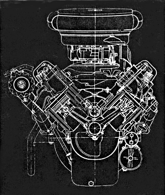
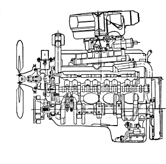
Transverse,
left, and longitudinal sections of the Packard V8
This
little feature could and should be used by a few other manufacturers. This dimension also allows the bore diameters to be enlarged at a
future date without scrapping the existing tooling. All that is
required is a relatively simple and inexpensive change in the coring
of the cylinders. Sufficient space in the underside of the block has
been provided for a substantial increase in crankshaft stroke, when
the need arises, without interference with the existing block casting
or other parts. The overall length of the cylinder block is 27 3/4
inches. From all outward appearances, the block could be safely
rebored to 4 1/8 inches with no particular danger from cylinder
distortion or overheating; on Packard and Clipper "Custom"
blocks, that is. The 3 13/16 inch bores of the Clipper "DeLuxe"
and "Super" blocks, as well as those of the Hudson and
Nash, could be bored to a maximum of 3 15/16 inches with reasonable
safety. Packard engineers went to considerable lengths to evaluate
the relative merits of forged versus cast crankshafts. According to
their findings, a steel casting provides a sufficiently high modulus
of elasticity as well as material density to effect a lighter
crankshaft without sacrifices in rigidity or stiffness. Also, a
casting permits the counterweights to be more favorably disposed for
balancing effectiveness, as well as coring of the crankpins to reduce
the amount of unbalance and, consequently the size of the
counterweights. The finished Packard V8 crank is a heat-treated
alloyed steel casting that weighs 56 pounds. The five main bearing
journals are ground to a diameter of 2.500 inches and the crankpins
are 2.250 inches in diameter. These dimensions are well within the
realm of design conservatism shown elsewhere in the engine. With the
3 1/2 inch stroke, an overlap of 5/8 of an inch is obtained between
the crankpins and adjacent main bearing journals, which materially
contribute to the torsional stiffness of the crank. The total
connecting rod effective bearing area is 52.8 square inches and the
total main bearing effective area is 38.6 square inches. A
non-bonded rubber harmonic balancer is placed at the nose of the
crank and is effective in reducing the amplitude of torsional
vibrations. The balancer is integral with the crankshaft pulley
assembly. Fore-and-aft crankshaft thrust loads are taken by the
flanged rear main bearing. The main bearings are copper-lead, while
connecting rod bearings are lead-babbitt, and both are of the
steel-backed replaceable insert type. Both bearing materials are
completely compatible with the heat-treated but unhardened steel
crank. Each connecting rod has its own bearing that is locked in the
rod and the crankshaft is drilled to oil each of the two bearings on
the crankpins. The healthy appearing connecting rods are drop
forgings made from SAE 1041 steel. The beam is of "H"
section design and the rods have a center-to-center length of 6 23/32
inches. Two specially formed high tensile steel bolts locate and
secure the rod cap to the rod. A groove is machined at the juncture
of rod and cap to provide lubrication from the rod bearings to the
cylinder walls on the opposite bank. Balancing lugs form integral
parts of the rod assembly, one lug at each end. A bronze piston pin
bushing is pressed into the small eye of the rod and is bored to give
.0002 of an inch clearance between the bushing and the pin. The
connecting rod assembly has undergone very severe testing at loads
and speeds, far in excess of those encountered in any type of driving
conditions. Each rod assembly weighs one pound 10 ounces. Aluminum
alloy "autothermic" pistons are used in which steel tension
members control the amount and direction of piston expansion. The
pistons "nest" about the crankshaft counterweights at the
bottom of the stroke, which necessitates a "slipper" type
skirt. Crown thickness of the flat-topped piston is .280 of an inch. Three ribs extend from the piston pin bosses to the crown for pin
boss rigidity. The .980 of an inch diameter by 3 1/4 inch long
piston pin is a full floating affair that is retained in the piston
by snap rings and grooves in the pin bosses. The pin material is
heat-treated SAE 1117 steel. The piston pin bores are offset 1/16 of
an inch in the direction of the major thrust face. Pistons are tin
plated to minimize "scuffing" during the initial break-in
period. Piston weight is one pound six ounces. Two compression
rings and one oil ring are used, all of which are located above the
piston pin. The alloy cast iron compression rings are 5/64 of an
inch wide with a radial thickness of .200 of an inch and have tapered
faces. The top ring is chrome plated to a thickness of from .004 to
.007 of an inch for longer, life and freedom from the effects of high
temperatures and corrosive gases.
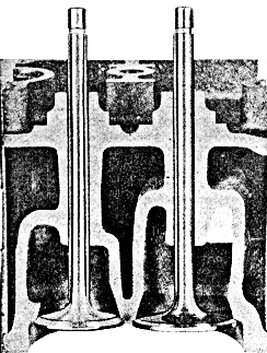
Cutaway
head shows generous passages, valve sizes and integral seat and guides.
The
alloy cast iron oil ring is of open slot design and measures 3/16 of
an inch in width with a radial thickness of .166 of an inch, and uses
a polygonally shaped light spring steel expander. The hardenable
alloy iron camshaft is driven by a one inch wide timing chain and
sprockets on the crank- and camshafts. The cam is supported in the
block by five removable steel-backed babbitt-coated bearings. The
cam lobes are ground with a taper of six minutes and are positioned
1/16 of an inch in back of the valve lifter centers to avoid lifter
overrun and insure positive lifter rotation. A helical gear, located
ahead of the rear bearing journal, is an integral part of the
camshaft and is used to drive the distributor. Hydraulic valve
lifters are used in all models, the bodies of which are Lubrite
coated hardenable iron. The lifter faces are ground to a spherical
radius of 30 inches and the lifter body diameter is .904 of an inch.
Lubriting the lifters and phosphate coating the camshaft is said to
minimize initial break-in wear, which seems to be the period when cam
and lifter wear is the most severe. In line with this, it is
interesting to note that, although the cams in all the Packard
engines are, to all intents and purposes, identical, cast steel
camshafts are specified for the engines supplied to Hudson and Nash. Even more interesting would be a comparison of the wearing qualities
of the two different camshaft materials, after each has been
subjected to long periods of operational service. But this we won't
know for a while. The cylinder head castings are made from the same
material as the block. They are interchangeable, left to right, and
each head weighs 64 pounds. Very generous water jacketing has been
provided around the ports, valves, spark plugs and combustion
chambers. Each head is located on the block by two dowels and is
secured by 15 cap screws, 7/16 of an inch in diameter, in a pattern
that surrounds each cylinder with five cap screws. Cylinder head
gaskets are of the embossed steel type, .025 of an inch thick. After
playing with many different combustion chamber configurations,
Packard chose the elliptically shaped, high turbulence "wedge"
type chamber. Tests have shown that, at compression ratios of 12 to
1, this design provides a low burning rate of the fuel/air mixture
charge and avoids a rapid pressure rise, thereby minimizing
combustion roughness, and the chamber is quite insensitive to
combustion chamber deposits usually incurred during low speed, light
load operation. "Quench" and "squish" areas,
formed by a .045 of an inch piston-to-cylinder head clearance, cover
20 per cent of the total piston area. Each combustion chamber is
fully machined, which makes for a consistent compression ratio for
all cylinders. The valve head diameters are unusually large for this
type of combustion chamber, being 1 15/16 inches for the intake
valves and 1 11/16 inches for the exhausts. This accounts for what
appears to be a slight "shrouding" of the valves at the
ends of the combustion chambers. The spark plug is located about 3/8
of an inch from the lateral axis of the cylinder bore toward the
intake valve on the deep side of the chamber. Due to the angular
location of the plug in the head, a counter-bored passage connects
the firing end of the plug with the main combustion chamber cavity. The present compression ratio of the Clipper and Packard engines is a
conservative 8 1/2 to 1, while the Hudson and Nash engines have an
even more conservative ratio of 7.8 to 1. If one chose to use the
heads of the 320-cubic inch Packard engine on the 352-cubic inch
engine, a compression ratio of 9 1/4 to 1 would be obtained, which
would be the upper limit for use with presently available gasolines. Or the heads may be milled .050 of an inch on the 352-cubic inch
engine for the same result. The same amount milled from the heads of
the Packard 320-cubic inch engine would result in a compression ratio
of 9.1 to 1. To obtain a compression ratio of 7.8 to 1 on the Hudson
and Nash, the heads from the 352-cubic inch engine are used. By
milling the Hudson and Nash heads .065 of an inch, the compression
ratio will be 8.7 to 1. When and if the heads are milled, each
side-of the intake manifold should be milled the same amount as the
heads to maintain correct intake port alignment. Also, the push rods
should be shortened by the amount milled from the heads. As future
fuels improve, it becomes a very simple matter of a coring and minor
tooling change to increase the compression ratio of the Packard
engine, which would undoubtedly be accomplished by lowering the
"roof" of the wedge type chamber.
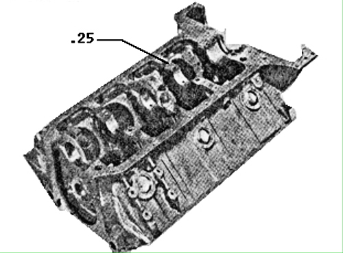 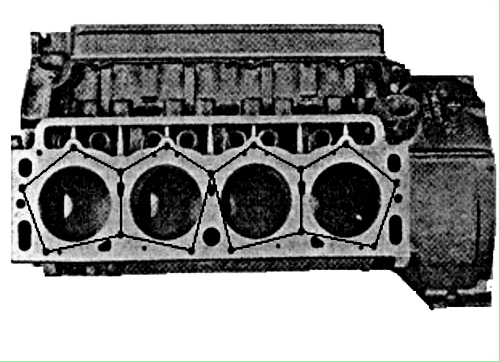
Left View: Bottom
of sturdy Packard V8 block has broached recesses for the positive
location of the five main bearing caps.
Right View: Cylinder
head cap screw pattern and the widely spaced bores provide a good
gasket seal with minimum block distortion.
As
previously mentioned, the valve sizes are quite generous, but much
more important for a high volumetric efficiency, the ports are
positively huge, especially on the intake side. As in other
comparable designs, the intake ports of the Packard cylinder heads
are rectangular in shape and arranged in pairs. Exhaust passages in
the heads have been laid out so that the two end cylinders of each
bank have individual ports, while the two center cylinders of each
bank discharge exhaust gases into common ports. Each center port has
a continuation extending upward and into the intake manifold pre-heat
chamber. Both intake and exhaust valve guides are an integral part
of the heads, which materially aid in reducing valve temperatures,
not only at the valve stems but at the seats as well. In fact, tests
involving the use of integral valve guides have shown that valve head
temperatures can be lowered as much as 200 degrees F., with a
corresponding reduction of valve stem temperature of 100 degrees F.,
as compared to the diminishing practice of using pressed-in guides,
which erect a thermal barrier despite the similarity of metals and
the proximity of the guides to the guide bores in the heads. Intake
valves are made from Silichrome number one steel, while the exhausts
are made from number 2112 austenitic steel. The valve seat angle is
30 degrees on the intake and 45 degrees on the exhausts. The
longitudinal axes of the valves form an angle of 12 degrees with the
longitudinal axes of the cylinder bores. The valves are retained by
conventional tapered split keepers, retainer washers and single valve
springs. In an effort to obtain a satisfactory valve motion in the
interests of good engine performance and yet not overload the nose of
the cam lobes, the Packard cam lobe shape results in a relatively low
rate of valve acceleration together with a low valve spring rate. The valve timing is as follows: Intake opens 14 degrees before top
center, closes 56 degrees after bottom center, duration 250 degrees,
lift at valve .375 is of an inch. Exhaust opens 52 degrees before
bottom center, closes 18 degrees after top center, duration 250
degrees, lift at valve .375 of an inch. The valve spring load is 82
pounds with the valve seated and 165 pounds with the valve open. The
rocker arms are cast pearlitic malleable iron with flame hardened
ends.
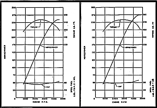
Brake
horsepower, torque and brake specific fuel consumption curves of the
standard 352-cubic inch Packard V8 engine, left, and the dual
four-throat "Caribbean," right.
These
are located on a single longitudinal rocker shaft for each head,
which is secured to the head by four rocker arm stands and four cap
screws. The rocker arm lift ratio is 1.6 to 1. Push rods are of
steel tubing with an outside diameter of 3/8 of an inch and a wall
thickness of .065 of an inch. These contain hardened steel tips that
arc ground to a spherical radius of 1/4 of an inch and are pressed
into the open ends of the push rods. Hydraulic valve lifter
"pump-up" speed is about 5100 rpm. Hm-m-m. With a little
intelligent work on the valve train, together with faster valve
action and more lift, one could more fully utilize the inherently
good "breathing" capacity of these engines. This might
require different cam and lifter material though. In the carburetion
department, there seems to be a great divergence of the engineering
minds. Hudson and Nash specify a single Carter WDG-223I-S two-throat
carburetor while the Clipper "DeLuxe" and "Super"
models call for a single Carter WCFB-2232-S four-throat. Both
Clipper "Customs" and Packards use a single Rochester '4GC
four-throat. The "Caribbean," Packard's answer to a
certain earth-bound space ship, employs two of the above Rochesters
on a well-designed, balanced intake manifold, which, incidentally,
will fit the other engines of the species. All of the carburetors
contain a thermostatically operated automatic choke which receives
heat from the intake manifold "stove." The intake
manifolds of the series are made from cast iron and have been
symmetrically designed in an attempt to equalize the lengths of the
passages. The carburetors receive fuel under a pressure of from 3
1/2 to 5 1/2 psi from a mechanical pump located on the right side of
the engine front cover. The pump is driven by a chrome plated,
hardened stamped steel eccentric that is bolted onto the front of the
camshaft sprocket. The unbalanced condition caused by the eccentric
is compensated for by the nonsymmetrical openings in the camshaft
sprocket. The fuel pump is one component that has been simplified in
the Packard design, for it no longer contains an integral vacuum
booster pump. But you'd never guess where said vacuum booster is
hiding. It's in the pan! Exhaust gases are collected by cast iron
manifolds that are positioned so that one won't get scorched changing
spark plugs on a hot engine. With the standard exhaust system, the
left-hand manifold connects to a two-inch diameter crossover pipe
that passes beneath the engine and joins to a 2 1/4-inch diameter
header pipe that extends to a reverse flow muffler. Tailpipe
diameter is two inches. With the optional dual' exhaust layout, the
header pipe diameter is two inches and the tailpipe diameter is 1 3/4
inches. Positive lubrication of the Packard engines is handled by a
spur gear type pump assembly with a built-in pressure relief valve. The pump is driven by an intermediate shaft that couples with the
distributor drive gear. Oil entering the pump through a screened
floating pickup is directed through a rather complex system of
galleries, drilled passages and headers to all main, connecting rod
and camshaft bearings, as well as valve lifter guide bores, rocker
shafts and arms, the timing chain and fuel pump eccentric. Other
parts are lubricated by splash or drain-back oil. A very sensibly
placed partial flow type oil filter is located on top of the engine
at the left front. This little gem of forethought makes changing the
filter cartridge an absolute joy rather than a tragedy. A constant
system pressure of 50 psi is maintained by the pressure' relief valve
under all normal operating conditions. The oil pump assembly isn't
complete without an eccentric vane-type vacuum booster pump for
windshield wiper operation under low vacuum conditions. The pump
performs double duty when the engine is idling because the pump
exhaust creates a pressure differential in the crankcase, which aids
in the circulation of air through the engine. To satisfy both the
present and future electrical requirements, particularly those of the
ignition and the starter motor, Packard has adopted a 12-volt system. Auto-Lite electrical systems are used on the small displacement
engines, while the big 'un employs Delco-Remy. The ignitions contain
centrifugal advance mechanisms as well as vacuum advance boosters. The starter motor and solenoid assembly is located at the rear of the
engine on the lower left side. The ignition is positioned at the
back of the engine to the left of center and is driven by a helical
gear that matches the gear on the camshaft. The pressurized cooling
system makes use of a single, high capacity centrifugal type pump
that is driven via pulleys and a 3/8 of an inch V-belt from the
crankshaft. The pump is mounted in a casting that resembles an
intake manifold for some strange four-banger. Coolant enters the pump
from the single lower radiator outlet, through an oil cooler for the
radiator. The heat rejection of the new engines to the coolant has
been reduced by about 21 per cent, as compared with the '54 straight
eight, which, in part, attests to the increased thermal efficiency of
the V8's. The method of balancing the engines is also of some
interest. Before assembly, all of the rotating and reciprocating
parts are individually balanced. This group includes the crankshaft,
connecting rod assemblies, piston assemblies, flywheels and harmonic
balancers. After the engine is put together, it is transferred to a
special balancing machine, which motors the engine sufficiently to
indicate the amount and location of unbalanced forces. The machine
automatically stops the engine at this point and the indicated
unbalance is compensated for by automatically drilling into the
crankshaft pulley and welding a slug onto the flywheel. Packard
claims that the stack-up of balancing tolerances that occurs during
engine assembly is reduced to no more than 1/4-inch-ounces by this
method. Could be, but I'd like to know how the balancing machine
compensates for the unbalanced forces that are absorbed by engine
friction while the engine is being motored. Oh, yes, almost forgot. The 352-cubic inch "Caribbean" engine is rated at 275 brake
horsepower at 4800 rpm and 355 pounds-feet of torque at 2800 rpm. This engine uses the previously mentioned double four-throat
manifold, carburetors and dual exhausts and is the most potent
automotive engine currently being produced in this country.
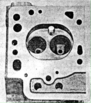
Fully
machined combustion chamber has been tested at compression ratio of
12:1.
|
